 Physics
📄 اطبع pdf
00971504825082
Refraction of light and lenses

"Light Refraction: The change in the direction of wave propagation when the wave moves from one medium to another
When refraction occurs, the wave speed changes
The wavelength changes when refraction occurs
The source is the same for both incident and refracted waves, meaning the frequency remains constant
Light Refraction
Write the appropriate number for each element based on the illustration
 Look at the image then write the appropriate number in each blank
Element
Number
The incident ray represents number
()
The refracted ray represents number
()
The angle of incidence represents number
()
The angle of refraction represents number
()
The perpendicular to the surface represents number
()
The interface surface represents number
()
Question: When does light refract toward the perpendicular?
When does it refract away from the perpendicular?
And when does refraction not occur?

Light falling from a medium with higher speed to a medium with lower speed
Light falling from a medium with lower speed to a medium with higher speed
Change the angle of incidence in both cases using the indicator and observe the results
Light Refraction Simulation
Explore how light refracts when moving between different media
Glass
Air
⚠️ Total internal reflection occurs

Snell's Law of Refraction
In 1621, Snell found that when light passes from one transparent medium to another, the sine of each angle is related through the equation:
\[n_1 . Sin (θ_1)=n_2 . Sin (θ_2)\]
\[n_1\] - refractive index of the first medium
\[n_2\] - refractive index of the second medium
\[θ_1\] - angle of incidence
\[θ_2\] - angle of refraction
🔍 Calculation Example:
When light travels from air (n=1) to water (n=1.33) at an incidence angle of 30°:
\[ sin(θ₂) = \frac{(1 × sin(30°))} {1.33} ≈ 0.3759\]
θ₂ ≈ 22°
Interactive Simulation
Results:
Practical Applications
1. Optical Fibers
Use the phenomenon of total internal reflection to transmit data through glass fibers with minimal energy loss
2. Medical Endoscopes
Used in internal endoscopy to examine internal organs without surgery
3. Optical Reflectors
Used in traffic signals and bicycles to effectively reflect light
4. Imaging Techniques
Applications in advanced optical microscopes and medical imaging

Refractive Index
It is the ratio between the speed of light in vacuum to the speed of light in that medium:
\[n=\frac{C}{v}\]
The refractive index has no unit of measurement because it's a ratio and is always greater than one because the speed of light in vacuum is always the greatest.
Material
Refractive Index (n)
Vacuum
1.00000
Air (at standard conditions)
1.00029
Water (20°C)
1.333
Ethanol
1.361
Polished Glass (Soda-lime glass)
1.52
Fused Quartz
1.46
Flint Glass
1.60 - 1.89
Note: The refractive index is the ratio between the speed of light in a vacuum and its speed in the material.
The mentioned values are at a temperature of 20°C and a wavelength of 589 nanometers (Sodium D-line).
Snell's Law
In this simulation, apply Snell's Law and verify the law's validity. Each time, change the medium and determine the angle of incidence, angle of refraction, refractive index of the first medium, and refractive index of the second medium. Apply Snell's Law and verify the equality.
In this simulation, change the refractive index using the slider on the right and calculate the refractive index and the angle at which the ray exits.
Critical Angle and Total Internal Reflection
Shine light from a medium with a higher refractive index to a medium with a lower refractive index and compare the angle of incidence and refraction.
The angle of incidence is (greater - smaller) than the angle of refraction.
Increase the angle of incidence until you reach a refraction angle of 90 degrees. At this point, we call the angle of incidence that corresponds to a refraction angle of 90 degrees the critical angle, denoted by the symbol \[θ_C\].

\[n_1 . Sin (θ_1)=n_2 . Sin (θ_2)\]
\[n_1 . Sin (θ_C)=n_2 . Sin (90)\]
\[ Sin (θ_C)=\frac{n_2}{n_1}\]
Solved Example
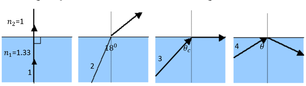
In the figure below, there are four cases of light falling from water to air.
Ray 1 did not undergo refraction. Why?
Calculate the refraction angle for ray 2.
Calculate the critical angle for ray 3.
Why did total internal reflection occur for ray 4?
 Click here to show solution method
Lenses
There are two types of lenses:
Convex lenses: Thin at the edges and thick in the middle
They converge rays if they fall parallel at a single point called the focus, which is real resulting from the intersection of refracted rays.

Concave lenses: Thick at the edges and thin in the middle
They diverge rays if they fall parallel, but the extensions of the refracted rays meet at a single point called the focus, which is imaginary resulting from the intersection of the extensions of refracted rays.

They have different shapes:

Focus

Images in Lenses
First, we need to know the path of rays in lenses.
All incident rays obey the law of refraction.
Light falling parallel to the principal axis refracts passing through the focus in convex lenses or its extension passes through the focus in concave lenses.

Light passing through the optical center continues its path without refraction.

Light passing through the focus as in convex lenses or its extension passing through the focus as in concave lenses refracts parallel to the principal axis.

Lenses
Lenses
In this simulation, we will place an object at different distances from convex and concave lenses, draw the formed images, and determine the image characteristics.
Drawing Skill
Complete drawing the images formed from the previous experiment when placing an object in front of a convex lens at different positions and verify the solution by clicking on the solution method.

Click here to show solution method
Complete drawing the images formed from the previous experiment when placing an object in front of a concave lens at any position. The same image appears. Verify the solution by clicking on the solution method.

Click here to show solution method
Useful Information: Lens Formulas
From the similarity of triangles, the lens equations are derived:
\[\dfrac{1}{X_o}+\dfrac{1}{X_i}=\dfrac{1}{f}\]
There is a problem in applying the previous equation, which is the signs of the previous values. The following table shows the signs:
In optics, we use positive and negative signs to indicate the positions of objects and images relative to lenses. The following table shows the signs of focal length, object distance, and image distance in convex and concave lenses.
Lens Type
Focal Length \[f\]
Object Distance \[X_O\]
Image Distance \[X_i\]
Notes
Convex Lens (Converging)
Positive (+)
Positive (+) if object is placed in front of lens
Negative (-) if object is an image from another lens
Positive (+) for real images
Negative (-) for virtual images
The image is real when the image forms on the opposite side of the lens
Concave Lens (Diverging)
Negative (-)
Positive (+) if object is placed in front of lens
Negative (-) if object is an image from another lens
Negative (-)
The image is always virtual, upright, and smaller than the object
We only assign signs to known values.
Magnification is the ratio of image height \[{h_i}\] to object height \[{h_o}\].
It is equivalent to (-) image distance to object distance.
\[M = \dfrac{h_i}{h_o} = -\dfrac{X_i}{X_o} \]
Note that the magnification sign is always opposite to the image distance sign.
Optical Lenses: Comprehensive Study
Optical Lenses: Comprehensive Study
First: Basic Concepts
1. Convex Lens
Convex lenses are characterized by being thicker in the middle than at the edges, and they work to converge light rays. Main characteristics:
- Positive focal length (f > 0)
- Produces real or virtual images depending on object position
- Used to correct farsightedness
2. Concave Lens
Concave lenses are characterized by being thinner in the middle than at the edges, and they work to diverge light rays. Main characteristics:
- Negative focal length (f < 0)
- Always produces virtual images
- Used to correct nearsightedness
Second: Lens Law
The lens law states the following relationship:
\[\frac {1}{f }=\frac {1}{X_I} +\frac {1}{X_O}\]
Where:
\[f \] - Focal length
\[X_i\] - Image distance
\[X_o\] - Object distance
Third: Comparison Between Lenses
Comparison Between Convex and Concave Lenses
Convex Lens Concave Lens
Definition
A lens that is thick in the middle and thin at the edges, refracts rays through it toward the center
Definition
A lens that is thin in the middle and thick at the edges, scatters rays away from the center
Image Type
Real or virtual
Image Type
Always virtual
Orientation
Inverted or upright
Orientation
Always upright
Basic Equations:
\[\frac {1}{f} = (n-1)(\frac {1}{R₁} - \frac {1}{R₂})\]
\[\frac {1}{f }=\frac {1}{X_I} + \frac {1}{X_O}\]
Magnification \[m =\frac {X_I}{X_O}\]
Positive focal length \[f\]
Refractive index \[ n\]
Basic Equations:
\[\frac {1}{f} = (n-1)(\frac {1}{R₁} - \frac {1}{R₂})\]
\[\frac {1}{f }=\frac {1}{X_I} +\frac {1}{X_O}\]
Magnification \[m =\frac {X_I}{X_O}\]
Negative focal length \[f\]
Refractive index \[ n\]
Practical Applications:
- Cameras and binoculars
- Microscopes and magnifiers
- Farsightedness glasses
- Astronomical telescopes
Practical Applications:
- Nearsightedness glasses
- Laser devices (beam expansion)
- Side lighting fixtures
- Door viewers (peepholes)
Fourth: Practical Applications
Applications of Convex Lenses:
- Photographic cameras
- Microscopes
- Farsightedness correction glasses
Applications of Concave Lenses:
- Nearsightedness correction glasses
- Car headlight systems
- Telescope systems
Lens Law Simulation
Lens Law Simulation
In this simulation, move the blue circle above the object to move the object. Move the circle at the focus to change the focal length. Move the blue circle to the right side of the lens to change it to a concave lens. Change the object position each time and determine the focal length value and object distance from the experiment, then calculate the image distance and magnification each time.
In this simulation, chromatic aberration is a type of image distortion resulting from the lens's inability to focus colors at the same convergence point.
It occurs due to the difference in the refractive index of lenses and the difference in light wavelengths.
It was found that the refractive index of glass media increases with wavelength, its value is greater for blue light than for red light.
In this simulation, spherical aberration is an optical effect
observed in optical devices, lenses, mirrors, and others that occurs due to increased
refraction of light rays falling on a lens or resulting from reflection of light rays
when they fall on a mirror near its edge, compared to rays that fall near the center. Scientists recognized this property of spherical surfaces
during the seventeenth century AD when they were trying to make a telescope with a concave spherical mirror
. After examination and scrutiny, they concluded that a parabolic surface serves the purpose, as it collects parallel incident rays at a single focus
. Mathematics and the parabola equation helped them with this.
This aberration intensifies at the focus
the closer the light ray falls to the edge of the mirror or the edge of the lens
. The rays gather at a point on the principal axis of the lens or the spherical surface at a distance from the "vertex" of the spherical curve
Refraction of light and lenses |
"Light Refraction: The change in the direction of wave propagation when the wave moves from one medium to another
When refraction occurs, the wave speed changes
The wavelength changes when refraction occurs
The source is the same for both incident and refracted waves, meaning the frequency remains constant
Light Refraction
Write the appropriate number for each element based on the illustration
Look at the image then write the appropriate number in each blank
| Element | Number |
|---|---|
| The incident ray represents number | () |
| The refracted ray represents number | () |
| The angle of incidence represents number | () |
| The angle of refraction represents number | () |
| The perpendicular to the surface represents number | () |
| The interface surface represents number | () |
Question: When does light refract toward the perpendicular?
When does it refract away from the perpendicular?
And when does refraction not occur?
Light falling from a medium with lower speed to a medium with higher speed
Change the angle of incidence in both cases using the indicator and observe the results
Light Refraction Simulation
Explore how light refracts when moving between different media
Snell's Law of Refraction
In 1621, Snell found that when light passes from one transparent medium to another, the sine of each angle is related through the equation:
\[n_1 . Sin (θ_1)=n_2 . Sin (θ_2)\]\[n_1\] - refractive index of the first medium
\[n_2\] - refractive index of the second medium
\[θ_1\] - angle of incidence
\[θ_2\] - angle of refraction
🔍 Calculation Example:
When light travels from air (n=1) to water (n=1.33) at an incidence angle of 30°:
\[ sin(θ₂) = \frac{(1 × sin(30°))} {1.33} ≈ 0.3759\]
θ₂ ≈ 22°
Interactive Simulation
Results:
Practical Applications
1. Optical Fibers
Use the phenomenon of total internal reflection to transmit data through glass fibers with minimal energy loss
2. Medical Endoscopes
Used in internal endoscopy to examine internal organs without surgery
3. Optical Reflectors
Used in traffic signals and bicycles to effectively reflect light
4. Imaging Techniques
Applications in advanced optical microscopes and medical imaging
Refractive Index
It is the ratio between the speed of light in vacuum to the speed of light in that medium:
\[n=\frac{C}{v}\]The refractive index has no unit of measurement because it's a ratio and is always greater than one because the speed of light in vacuum is always the greatest.
| Material | Refractive Index (n) |
|---|---|
| Vacuum | 1.00000 |
| Air (at standard conditions) | 1.00029 |
| Water (20°C) | 1.333 |
| Ethanol | 1.361 |
| Polished Glass (Soda-lime glass) | 1.52 |
| Fused Quartz | 1.46 |
| Flint Glass | 1.60 - 1.89 |
Snell's Law
In this simulation, apply Snell's Law and verify the law's validity. Each time, change the medium and determine the angle of incidence, angle of refraction, refractive index of the first medium, and refractive index of the second medium. Apply Snell's Law and verify the equality.
In this simulation, change the refractive index using the slider on the right and calculate the refractive index and the angle at which the ray exits.
Critical Angle and Total Internal Reflection
Shine light from a medium with a higher refractive index to a medium with a lower refractive index and compare the angle of incidence and refraction.
The angle of incidence is (greater - smaller) than the angle of refraction.
Increase the angle of incidence until you reach a refraction angle of 90 degrees. At this point, we call the angle of incidence that corresponds to a refraction angle of 90 degrees the critical angle, denoted by the symbol \[θ_C\].
\[n_1 . Sin (θ_1)=n_2 . Sin (θ_2)\]
\[n_1 . Sin (θ_C)=n_2 . Sin (90)\]
\[ Sin (θ_C)=\frac{n_2}{n_1}\]
Solved Example
In the figure below, there are four cases of light falling from water to air.
Ray 1 did not undergo refraction. Why?
Calculate the refraction angle for ray 2.
Calculate the critical angle for ray 3.
Why did total internal reflection occur for ray 4?
Click here to show solution method
Lenses
There are two types of lenses:
Convex lenses: Thin at the edges and thick in the middle
They converge rays if they fall parallel at a single point called the focus, which is real resulting from the intersection of refracted rays.
Concave lenses: Thick at the edges and thin in the middle
They diverge rays if they fall parallel, but the extensions of the refracted rays meet at a single point called the focus, which is imaginary resulting from the intersection of the extensions of refracted rays.
They have different shapes:
Focus
Images in Lenses
First, we need to know the path of rays in lenses.
All incident rays obey the law of refraction.
Light falling parallel to the principal axis refracts passing through the focus in convex lenses or its extension passes through the focus in concave lenses.
Light passing through the optical center continues its path without refraction.
Light passing through the focus as in convex lenses or its extension passing through the focus as in concave lenses refracts parallel to the principal axis.
Lenses
In this simulation, we will place an object at different distances from convex and concave lenses, draw the formed images, and determine the image characteristics.
Drawing Skill
Complete drawing the images formed from the previous experiment when placing an object in front of a convex lens at different positions and verify the solution by clicking on the solution method.
Click here to show solution method
From the similarity of triangles, the lens equations are derived:
\[\dfrac{1}{X_o}+\dfrac{1}{X_i}=\dfrac{1}{f}\]
There is a problem in applying the previous equation, which is the signs of the previous values. The following table shows the signs:
In optics, we use positive and negative signs to indicate the positions of objects and images relative to lenses. The following table shows the signs of focal length, object distance, and image distance in convex and concave lenses.
| Lens Type | Focal Length \[f\] | Object Distance \[X_O\] | Image Distance \[X_i\] | Notes |
|---|---|---|---|---|
| Convex Lens (Converging) | Positive (+) | Positive (+) if object is placed in front of lens Negative (-) if object is an image from another lens |
Positive (+) for real images Negative (-) for virtual images |
The image is real when the image forms on the opposite side of the lens |
| Concave Lens (Diverging) | Negative (-) | Positive (+) if object is placed in front of lens Negative (-) if object is an image from another lens |
Negative (-) | The image is always virtual, upright, and smaller than the object |
We only assign signs to known values.
Magnification is the ratio of image height \[{h_i}\] to object height \[{h_o}\].
It is equivalent to (-) image distance to object distance.
\[M = \dfrac{h_i}{h_o} = -\dfrac{X_i}{X_o} \]
Note that the magnification sign is always opposite to the image distance sign.
Optical Lenses: Comprehensive Study
First: Basic Concepts
1. Convex Lens
Convex lenses are characterized by being thicker in the middle than at the edges, and they work to converge light rays. Main characteristics:
- Positive focal length (f > 0)
- Produces real or virtual images depending on object position
- Used to correct farsightedness
2. Concave Lens
Concave lenses are characterized by being thinner in the middle than at the edges, and they work to diverge light rays. Main characteristics:
- Negative focal length (f < 0)
- Always produces virtual images
- Used to correct nearsightedness
Second: Lens Law
The lens law states the following relationship:
Where:
\[f \] - Focal length
\[X_i\] - Image distance
\[X_o\] - Object distance
Third: Comparison Between Lenses
Comparison Between Convex and Concave Lenses
DefinitionA lens that is thick in the middle and thin at the edges, refracts rays through it toward the center |
DefinitionA lens that is thin in the middle and thick at the edges, scatters rays away from the center |
Image TypeReal or virtual |
Image TypeAlways virtual |
OrientationInverted or upright |
OrientationAlways upright |
Basic Equations:
\[\frac {1}{f} = (n-1)(\frac {1}{R₁} - \frac {1}{R₂})\]
Positive focal length \[f\]\[\frac {1}{f }=\frac {1}{X_I} + \frac {1}{X_O}\] Magnification \[m =\frac {X_I}{X_O}\] Refractive index \[ n\] |
Basic Equations:
\[\frac {1}{f} = (n-1)(\frac {1}{R₁} - \frac {1}{R₂})\]
Negative focal length \[f\]\[\frac {1}{f }=\frac {1}{X_I} +\frac {1}{X_O}\] Magnification \[m =\frac {X_I}{X_O}\] Refractive index \[ n\] |
Practical Applications:
|
Practical Applications:
|
Fourth: Practical Applications
Applications of Convex Lenses:
- Photographic cameras
- Microscopes
- Farsightedness correction glasses
Applications of Concave Lenses:
- Nearsightedness correction glasses
- Car headlight systems
- Telescope systems
Lens Law Simulation
It occurs due to the difference in the refractive index of lenses and the difference in light wavelengths.
It was found that the refractive index of glass media increases with wavelength, its value is greater for blue light than for red light.
observed in optical devices, lenses, mirrors, and others that occurs due to increased
refraction of light rays falling on a lens or resulting from reflection of light rays
when they fall on a mirror near its edge, compared to rays that fall near the center. Scientists recognized this property of spherical surfaces
during the seventeenth century AD when they were trying to make a telescope with a concave spherical mirror
. After examination and scrutiny, they concluded that a parabolic surface serves the purpose, as it collects parallel incident rays at a single focus
. Mathematics and the parabola equation helped them with this. This aberration intensifies at the focus
the closer the light ray falls to the edge of the mirror or the edge of the lens
. The rays gather at a point on the principal axis of the lens or the spherical surface at a distance from the "vertex" of the spherical curve
No comments:
Post a Comment